Asperitas Logo
Environment / Bioplastic / Product

Biopatch

A biomass-derived hydrogel patch platform. Biopatch couples an alginate–polyacrylamide double-network matrix with a ROS-modulating botanical extract and an integrated strain-sensing layer, so a dressing can both act on the wound environment and report the mechanical load applied to it.

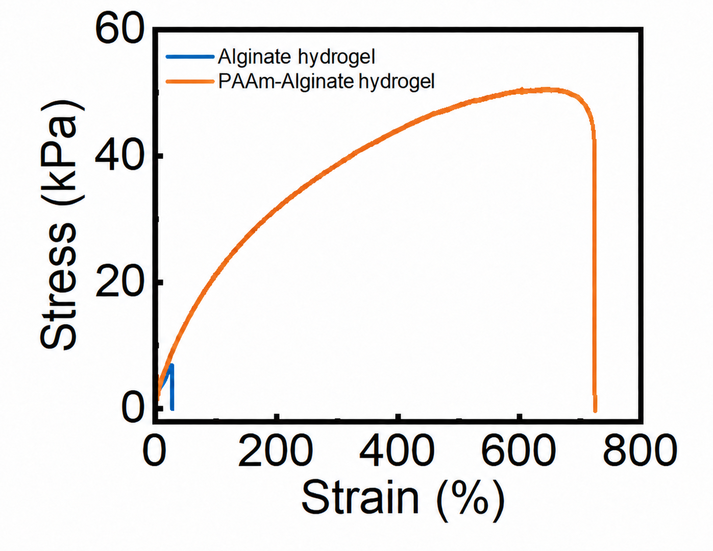
~700% Tensile strain at failure
~50 kPa Maximum tensile stress
85% ROS signal vs. control at 500 µg/mL
20 Hz Resistance readout refresh
The problem

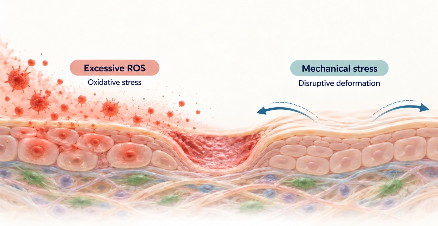
Chronic wounds fail for two reasons at once, and conventional dressings address neither.

A wound that will not close is usually held in an unfavourable biochemical state. Sustained oxidative stress keeps the tissue in a pro-inflammatory loop, and excess reactive oxygen species have been linked experimentally to the onset and persistence of chronic wounds. A passive dressing covers that environment without changing it.

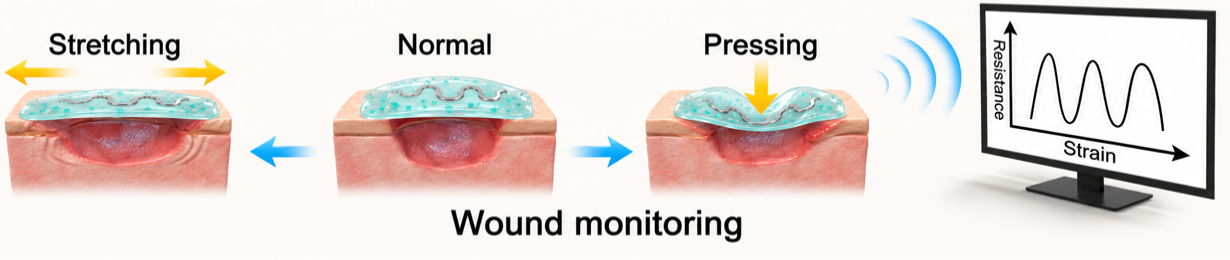
The second failure mode is mechanical. Repeated deformation at the wound margin is associated with delayed closure and heightened inflammation, and it is invisible to the clinician between dressing changes. Biopatch was specified to address both: a matrix that carries ROS-reducing chemistry, and a sensing layer that makes local mechanical load a measurable quantity.

Two failure modes in chronic wound repair: excessive reactive oxygen species and sustained mechanical stress at the wound margin.
Platform

One feedstock class, two functions: structural matrix and candidate bioactive.

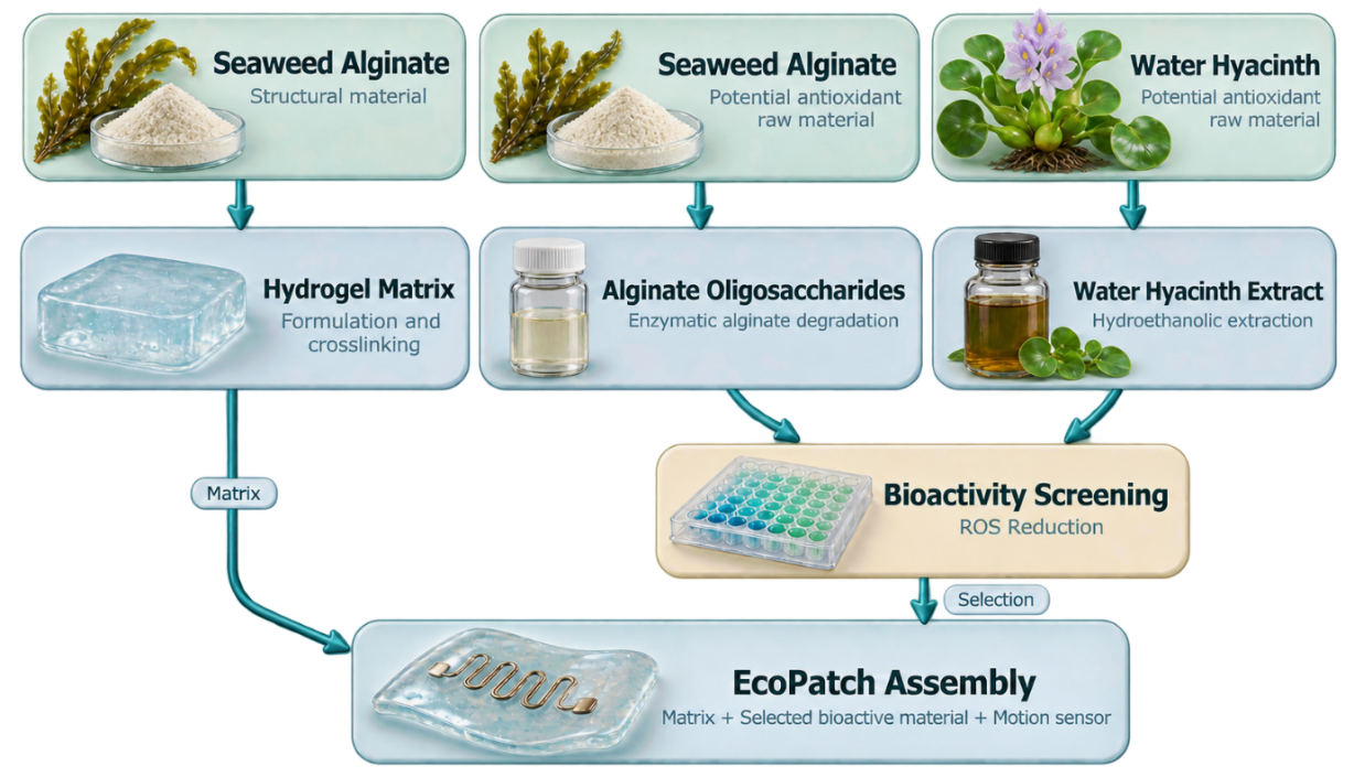
Biopatch is built from aquatic biomass. Seaweed-derived alginate serves twice over, as the hydrogel matrix and as the substrate for enzymatic production of alginate oligosaccharides. Water hyacinth, an invasive freshwater macrophyte whose dense mats depress dissolved oxygen and degrade habitat, supplies the second candidate ingredient through hydroethanolic extraction.

Both candidates enter the same cell-based screen. The selected ingredient is then carried into matrix fabrication, and the sensing layer is deposited on the finished patch. Each stage is specified as an independently testable unit, so a result at one stage does not have to be inferred from the behaviour of the assembled device.

Development workflow: alginate supplies matrix and enzyme substrate, water hyacinth supplies extract, both are screened for ROS activity before patch integration.
/01

Conversion

Recombinant alginate lyases depolymerise sodium alginate into oligosaccharide fractions.

/02

Extraction

Water hyacinth biomass is washed, dried, milled and extracted in 50% hydroethanol.

/03

Screening

Candidates are compared in an LPS-induced ROS assay in a macrophage line.

/04

Integration

The selected extract is loaded into the double-network matrix and the sensing layer applied.

Feedstock

Alginate for structure. An invasive macrophyte for chemistry.

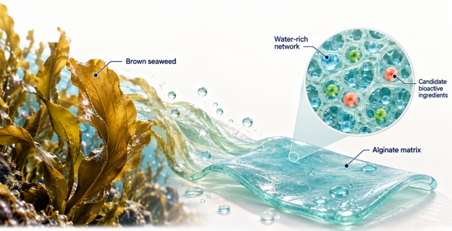
Alginate is an abundant, biocompatible polysaccharide recovered from brown seaweed. Its hydrophilic carboxylate groups drive hydration and swelling, which is the behaviour a wound-contact material needs, and the same carboxylates provide the ionic crosslinking sites used later in fabrication. Seaweed is cultivated without arable land or fresh water.

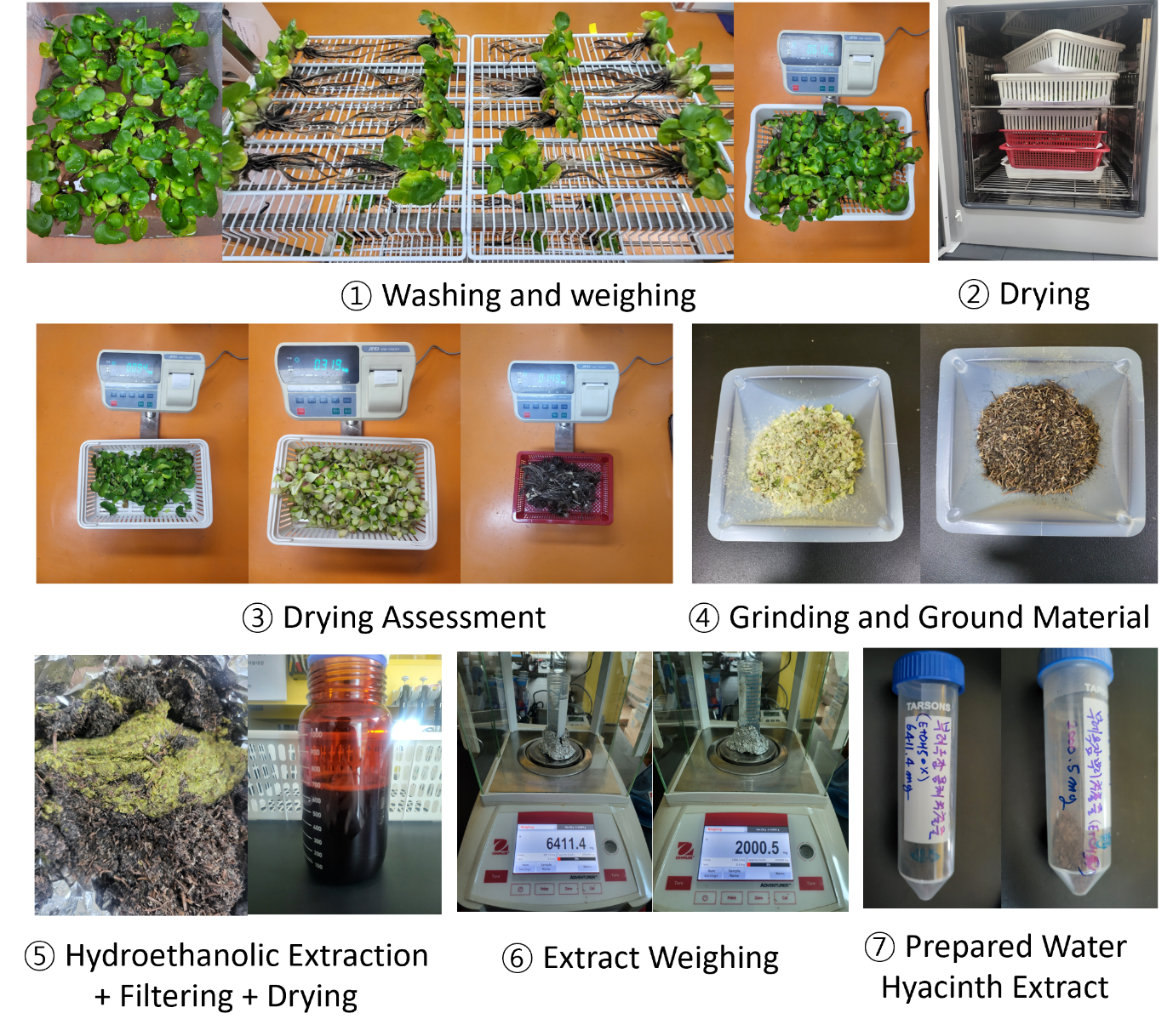
Water hyacinth is handled as a liability converted into an input. Biomass is washed, separated, dried at 60 °C and ground, then extracted in 50% hydroethanol at a 30-fold w/v ratio over 72 hours. Material provenance is treated as a specification rather than a claim: traceable origin, removal purpose and handling records are prerequisites for any sourcing statement, and the process must not create an incentive to cultivate the plant.

Properties of an alginate-based hydrogel relevant to wound contact.
Process for extracting bioactive compounds from water hyacinth biomass.
Enzymatic conversion

Three alginate lyases screened for soluble expression, two carried forward.

Alginate depolymerisation is run with recombinant lyases expressed in E. coli BL21(DE3). Three constructs were evaluated against an empty-vector background: FlAlyA (PDB 5Y33) from Flavobacterium sp., Alyw203 from Vibrio sp., and AlgL7 from Microbulbifer sp. Expression was screened across three temperatures and two inducer concentrations in parallel, so favourable conditions were identified without iterating the design cycle three times over.

5Y33 and Alyw203 both yielded soluble protein at 18 °C and 26 °C; AlgL7 expressed poorly under every condition tested and was dropped. The two surviving candidates were run at 26 °C and 0.2 mM IPTG for functional work. Alyw203 showed a temperature-dependent shift in apparent mass, consistent with proteolytic cleavage near the fusion junction at lower temperatures, which remains an open question rather than a settled mechanism.

ConstructEnzyme originExpected massSoluble expressionStatus
5Y33Flavobacterium sp. FlAlyA43.5 kDa18 °C, 26 °CCarried forward
Alyw203Vibrio sp. W270.4 kDa18 °C, 26 °CCarried forward
AlgL7Microbulbifer sp. ALW175.7 kDaNone observedDiscontinued
Empty vector10×His–Smt3 tag only13.5 kDaBackground controlControl

Expression screened at 18 °C / 16 h, 26 °C / 6 h and 37 °C / 4 h, each at 0, 0.2 and 1.0 mM IPTG.

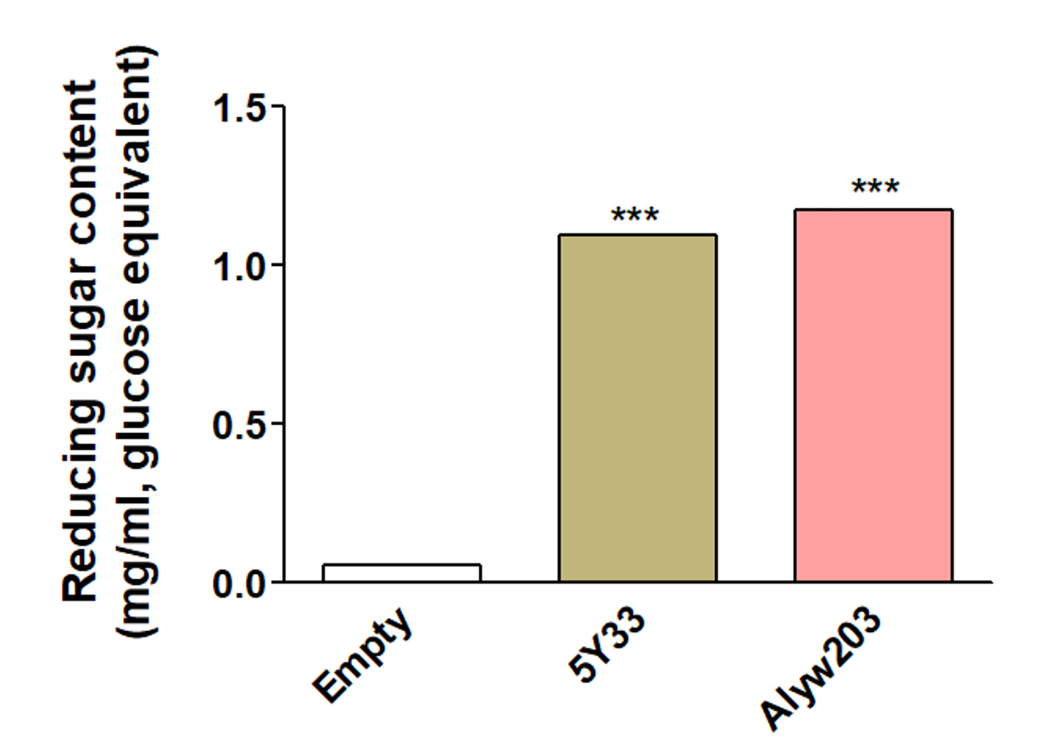
Depolymerisation was confirmed by dinitrosalicylic acid assay. Reactions containing either enzyme generated significantly higher reducing-sugar equivalents than the empty-vector control, which establishes that alginate was cleaved. Reducing-sugar equivalents are a measure of cleavage activity and are not a yield figure for isolated oligosaccharide.

Dinitrosalicylic acid assay results comparing alginate degradation by two recombinant lyases against an empty-vector control.
Bioactivity screening

The screen selected the extract and rejected the oligosaccharide route.

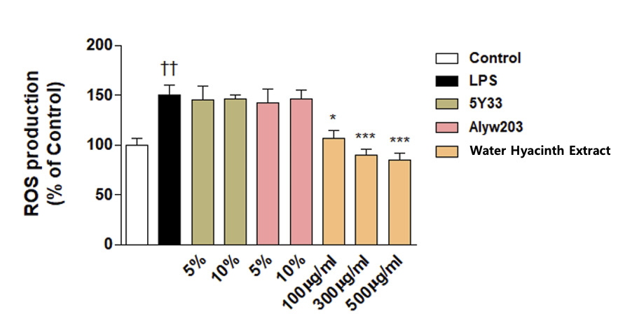
Both candidate ingredients were assayed for intracellular ROS in LPS-stimulated RAW 264.7 macrophages using a dichlorodihydrofluorescein diacetate probe, read at 485/528 nm across five replicates. The oligosaccharide preparations produced no significant reduction at either tested loading. The botanical extract produced a concentration-dependent reduction, falling below the unstimulated control at the two higher concentrations.

That result set the formulation. Extract at 100 µg/mL was selected for matrix loading, the concentration at which the LPS-induced signal is suppressed to approximately the level of untreated cells. The oligosaccharide route is not closed, but it requires different preparation conditions and concentrations before it can be assessed again.

TreatmentROS signal, % of controlSDOutcome
Unstimulated control100.014.3Reference
LPS only150.520.5Induction confirmed
AOS (5Y33), 5% v/v145.629.3No significant reduction
AOS (5Y33), 10% v/v146.39.5No significant reduction
AOS (Alyw203), 5% v/v141.832.4No significant reduction
AOS (Alyw203), 10% v/v146.319.4No significant reduction
Extract, 100 µg/mL106.718.3Selected for loading
Extract, 300 µg/mL90.013.5Dose response
Extract, 500 µg/mL84.915.1Dose response

Values normalised to the unstimulated control; n=5 per group. Significance by ANOVA with Dunnett's multiple comparison test.

ROS-reducing effect of oligosaccharide preparations and botanical extract in LPS-stimulated macrophages.
Matrix engineering

A single ionic network is too brittle for a surface that moves. So we built two.

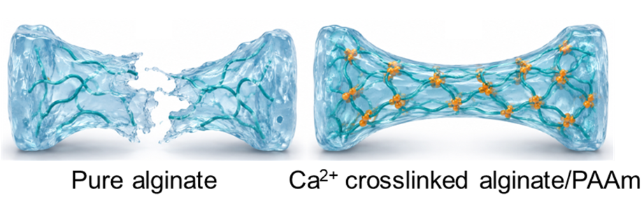
Calcium-mediated gelation converts soluble sodium alginate into a physically crosslinked hydrogel: divalent ions bridge carboxylate groups on adjacent chains in the configuration described by the egg-box model. The network forms quickly and absorbs water well, but an alginate-only gel fails in brittle fashion at low strain, which disqualifies it for a patch exposed to repeated movement.

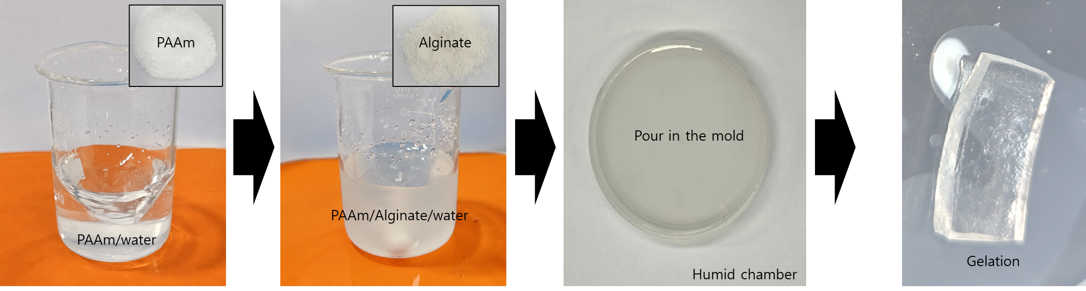
The production matrix is a double network. A covalently crosslinked polyacrylamide network is polymerised throughout the alginate-containing precursor, after which the cast gel is immersed in calcium chloride to form the ionic alginate network as the second phase. Under load the ionic network dissipates energy while the covalent network preserves continuity and shape. Calcium promotes gelation in the alginate phase only; it does not crosslink the polyacrylamide.

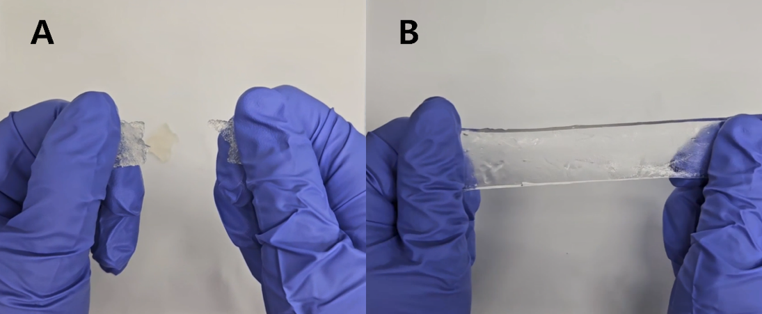
The effect is not marginal. Where the alginate-only gel fails early, the double network sustains approximately 700% strain and reaches roughly 50 kPa maximum tensile stress, while retaining the hydration behaviour that made alginate the matrix of choice.

Polymer network structures of alginate alone and of a calcium-crosslinked alginate-polyacrylamide double network.
Fabrication route for the calcium-crosslinked alginate-polyacrylamide double-network hydrogel.
Mechanical comparison of alginate and alginate-polyacrylamide hydrogels under tensile loading.
Stress-strain curves of alginate and polyacrylamide-alginate hydrogels under tensile loading.
Sensing layer

Deformation becomes a resistance trace, in real time.

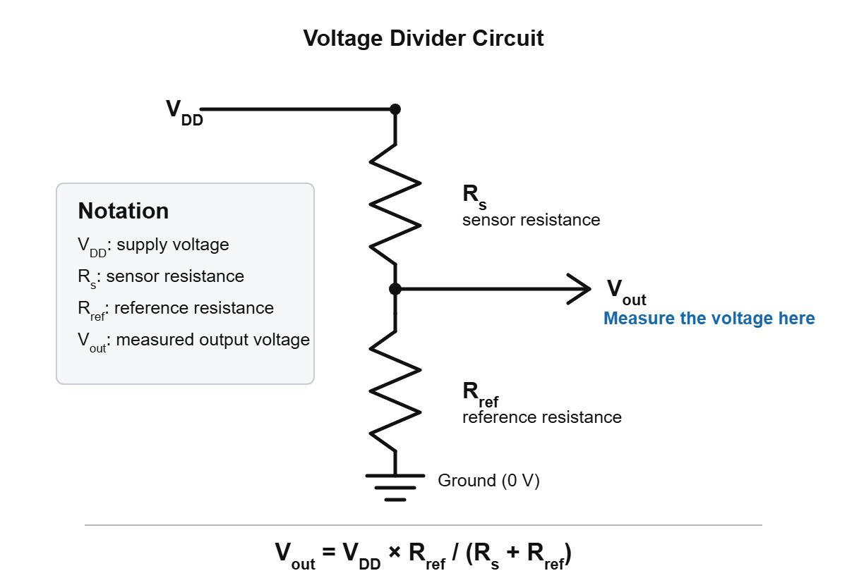
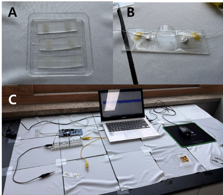
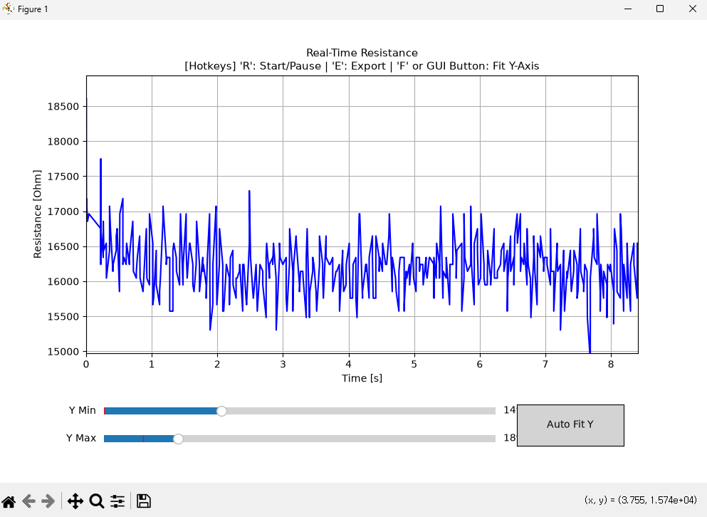
A flexible silver nanowire layer is deposited on the patch as a strain gauge. Bending, stretching and repeated deformation change its resistance; the patch is wired as the variable leg of a voltage divider against a 1 kΩ fixed reference, and the divider output is digitised by the analogue-to-digital converter of an nRF52840 microcontroller and streamed over USB serial at 115200 baud.

Resistance is recovered from the measured voltage by rearranging the divider relation, and plotted continuously in a ten-second moving window refreshed every 50 ms. The conversion path is deliberately transparent: the converter measures a voltage, the software computes a resistance, and the resistance trace is the quantity used to compare deformation events. Raw voltage is never treated as the sensor output.

Rs = Rref × ( VDD / Vout − 1 )    with Rref = 1000 Ω, VDD = 3000 mV
ComponentFunctionOutput
AgNW strain layerConverts deformation into a resistance changeVariable resistance Rs
Voltage dividerConverts resistance into a measurable voltageAnalogue voltage Vout
nRF52840 moduleSupplies VDD, samples the divider, transmitsSerial data at 115200 baud
Acquisition softwareComputes resistance and renders the traceResistance versus time, 20 Hz
Schematic of mechanical strain monitoring at a wound site using the patch.
Voltage divider circuit model used to convert sensor resistance into a measurable voltage.
Hardware configuration of the strain-sensing platform, including the coated patch, flexible prototype and acquisition setup.
Live resistance-versus-time display computed from the measured voltage stream.
BAUDRATE = 115200 # serial link to the acquisition module VDD = 3000.0 # supply voltage, millivolts R_REF = 1000.0 # fixed reference resistance, ohms WINDOW_SEC = 10 # moving display window, seconds PLOT_INTERVAL = 0.05 # redraw interval, seconds def calculate_resistance(voltage): return R_REF * (VDD / voltage - 1.0)

Once an unloaded baseline R0 is recorded, the same path yields relative change ΔR/R0 for comparison between deformation trials. The computation assumes a stable supply, a constant reference resistor and reliable contacts, and it reports absolute resistance rather than a calibrated strain figure.

Modelling

Three models, coupled only where the physics couples.

The platform carries an electrical model, a release model and a ROS model. They share parameters only where a shared parameter is physically justified: matrix thickness governs molecular transport, while the nanowire resistance model describes an electrically independent layer. Keeping them separate prevents a convenient result in one domain from propagating into another.

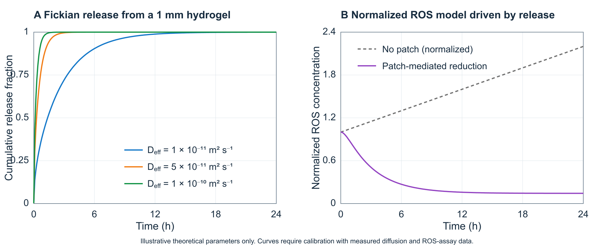
Release is approximated as one-dimensional Fickian diffusion through the matrix thickness, with an effective diffusion coefficient for the double network and release from both faces of the sheet. Stronger ionic crosslinking enters the model as a lower effective diffusivity where release data support it. The ROS model is a reaction–diffusion balance in which a source term represents continued generation at an inflamed site and a scavenging term scales with the locally available agent.

∂C/∂t = Deff ∂²C/∂x²    ·    dR/dt = PR − kscav · A(t) · R

The coupling is one-directional and physically ordered: the matrix must release the agent before the agent can act, so the diffusion model supplies the availability term A(t) to the ROS model. Faster release brings the effect forward in time; slower release spreads it out. The parameter set below is illustrative, used to interrogate design choices such as thickness and crosslink density, and every value requires wet-lab calibration before it describes a real wound.

ParameterIllustrative valueCalibration measurement
Matrix thickness, L1 mmMeasured patch thickness
Effective diffusivity, Deff1×10⁻¹¹ – 1×10⁻¹⁰ m² s⁻¹Release profile in buffer
ROS source, P0.05 normalised units h⁻¹Baseline generation condition
Scavenging constant, k0.35 h⁻¹ROS assay across concentrations
Simulated cumulative release at three diffusion coefficients, and the resulting normalised ROS trajectory.